39
they have to pass through switch L and switch H to
get
access
to
switch
E
and
then to switch B; too many hops means less performance.
Each switch representing each division, except for switch G, Y, I and switch O,
P,
Q
and
switch
V,
W
that
handle
1
division.
In
here,
all
devices
use
a
same
network
of
IP
Address
and
they
connect
with
others,
so
less
security
in
the
system because, nobody knows
if there
is an
inside
intruders
in the company that
can
use
some
application
to
sniff
and
look
around
the
data
in
other
division.
High
broadcast
traffic
can
occurred because
each
node
broadcasting
to others,
there is no broadcast domain. The real data can be seen in the figure 3.3.
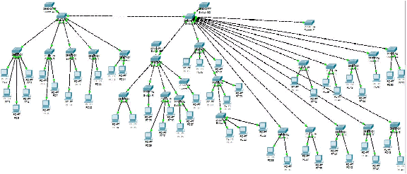
5.3
VLAN Simulation
Author has designed the VLAN topology like in the figure 4.4 that there are 3
clustering
core
switches,
which
are
switch
A, switch
B,
and
switch
E.
The
distribution
switches
that
connected
will
follow
them
to
the
ports
of
switch.
Here is the VLAN topology that is simulated using Packet Tracer:
Figure 5.2 VLAN Simulation